DB1. ER Diagram

Introduction
An entity-relationship (ER) diagram, also called an entity-relationship model shows the connection between entities.
here are two kinds of ER diagrams: conceptual and physical.
Conceptual ER Diagrams
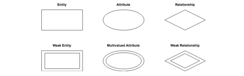
A conceptual ER diagram uses six standard symbols.
Entities are objects or concepts that represent important data. Also known as strong entities or parent entities, these entities will often have weak entities that depend on them.
Attributes are characteristics of an entity (i.e., many-to-many or one-to-one).
Relationships are associations between entities.
Weak entities depend on another entity.
Multivalued attributes are attributes that can have more than one value.
Weak relationships are the connections between a weak entity and its parent.
Physical ER Diagrams
Physical diagram models are more granular, showing the processes necessary for adding information to a database. Rather than using symbols, they consist of a series of tables.
Each entity is represented as a table, with each field acting as an attribute of the entity containing it.
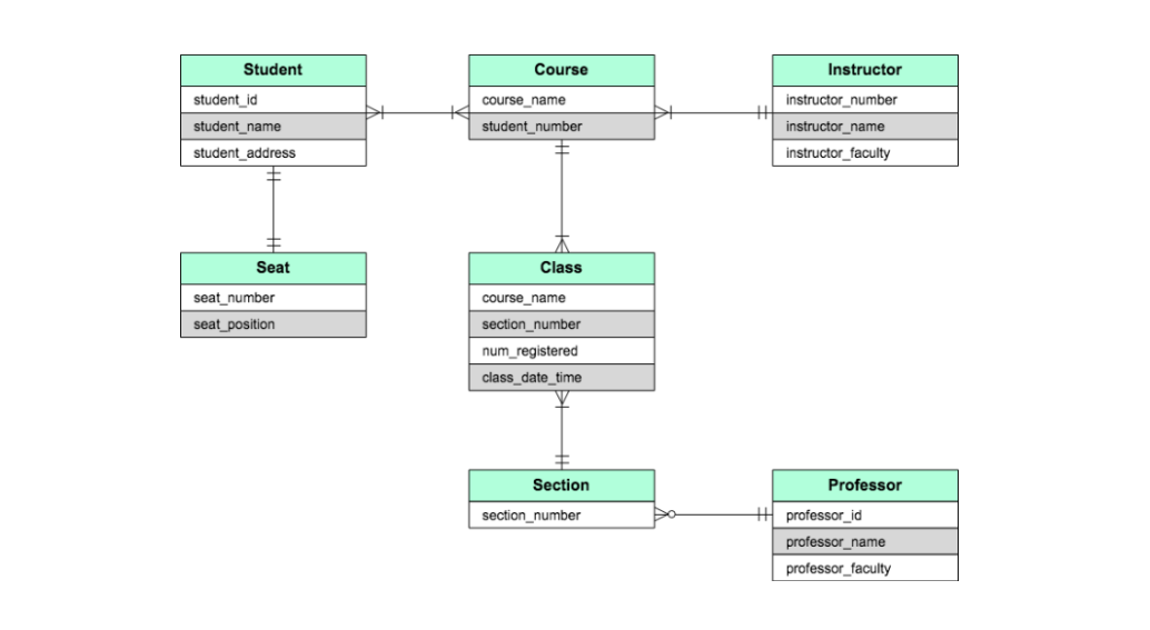
Entities are connected via a system of notation called crow’s foot notation. The styling of the endpoint of each line distinguishes the relationship.
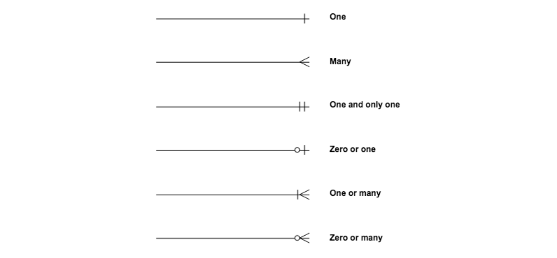
The types of relationships in an ER diagram depend on the entity’s interactions with the other elements. Relationships can be one-to-one (1:1) or one-to-many (1:N). In some instances, the relationship will include many to many (N:N).